For many years we have had the twin solenoid machines (Peco, Gem, Tenshodo), then along came the motor driven screw machines (Fulgarex, MannMade), then the stall motors (Switch Master, Tortoise, Cobalt).
All this time other modellers have just been using a single unit to do all the motion and animation duties on their models, model boats, model planes, and model automobiles (cars). Introducing the SERVO – it is quiet, powerful, reliable and very easy to adjust – easier than turning the volume up and down on your TV. For us Railroad Modelers, the big plus is its small size, the downside is the need for a piece of circuitry to “drive” the servo.
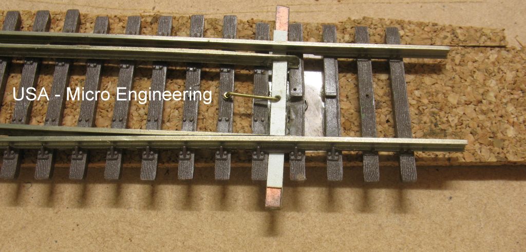
The cost of a servo is relatively low, the most common servo (SG90) can cost between $2.50 and $30.00 depending on where you get it. The Tam Valley Singlet II driver board used in the example below costs around $11.00. For those unfamiliar with using a servo to throw a point (turnout) or semaphore signal. They can be mounted on top of the baseboard, under the baseboard like a Switch Master – using a 1.0mm hole, or like a Tortoise or Cobalt – using a 2mm x 4mm hole.
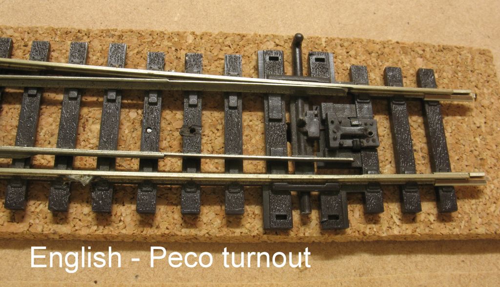
Peco turnout with a normal Tortoise style installation.
The tension on the centring spring has been reduced by sliding the “T” piece away from the throw bar.
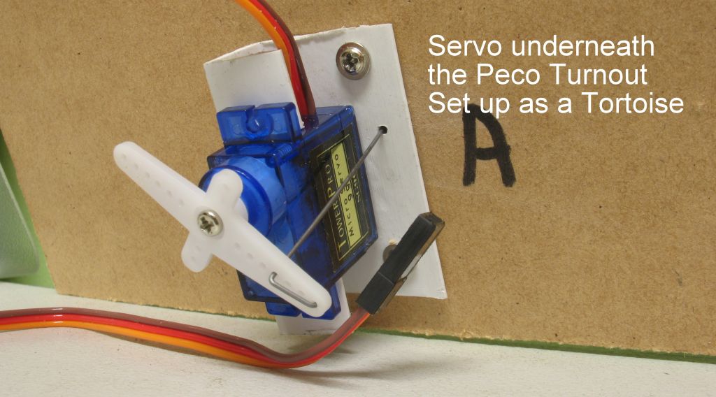
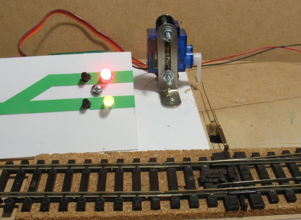
The servo operates in the same way as a Tortoise.
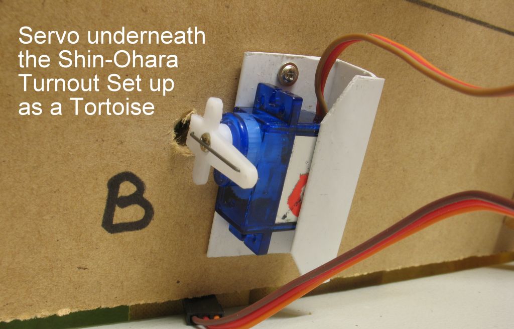
Once you are satisfied with the position, two small screws can then be inserted to hold it permanently in place. The screws supplied with the servo are perfect.
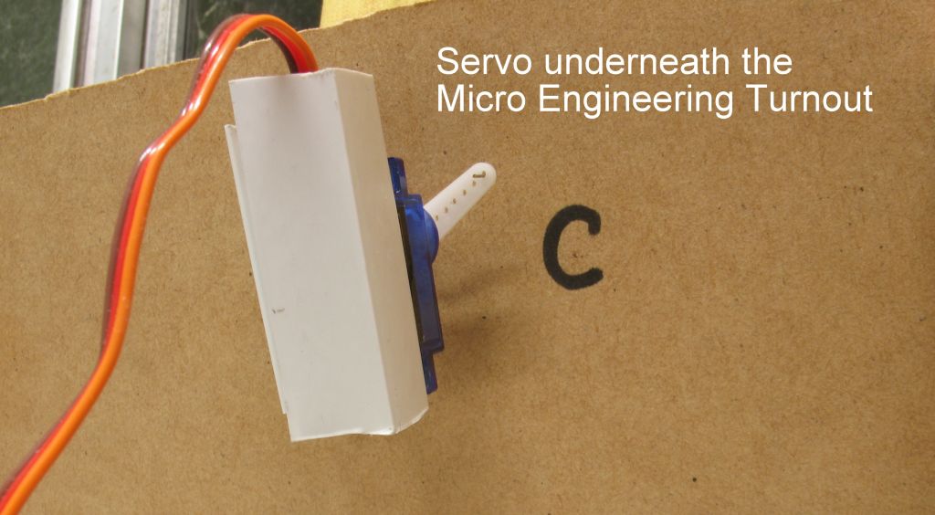
In all the photos the white plastic bracket is a short length of channel cut from a 3 metre length purchased from Bunnings (hardware chain store) for about $5.00. There is a short piece of thin double-sided tape between the screws that hold the bracket in position until you put the screws in. The screws come with the Servo.
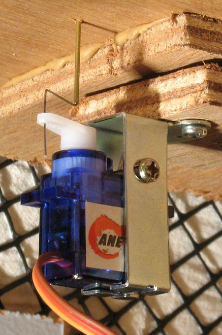
Here you can see the metal bracket from ANE mounting the servo in a hard to get at the spot under the layout.
Whichever method is used, the driver can drive the servo with precision, speed and silence with very little effort in the setup of the servo or the driver board. The servo is lightweight and easy to mount.
This is done in a “neutral” position (point blades centred) and the servo is then plugged onto the driver board with a 3 pin plug – all servos come with the same plug.
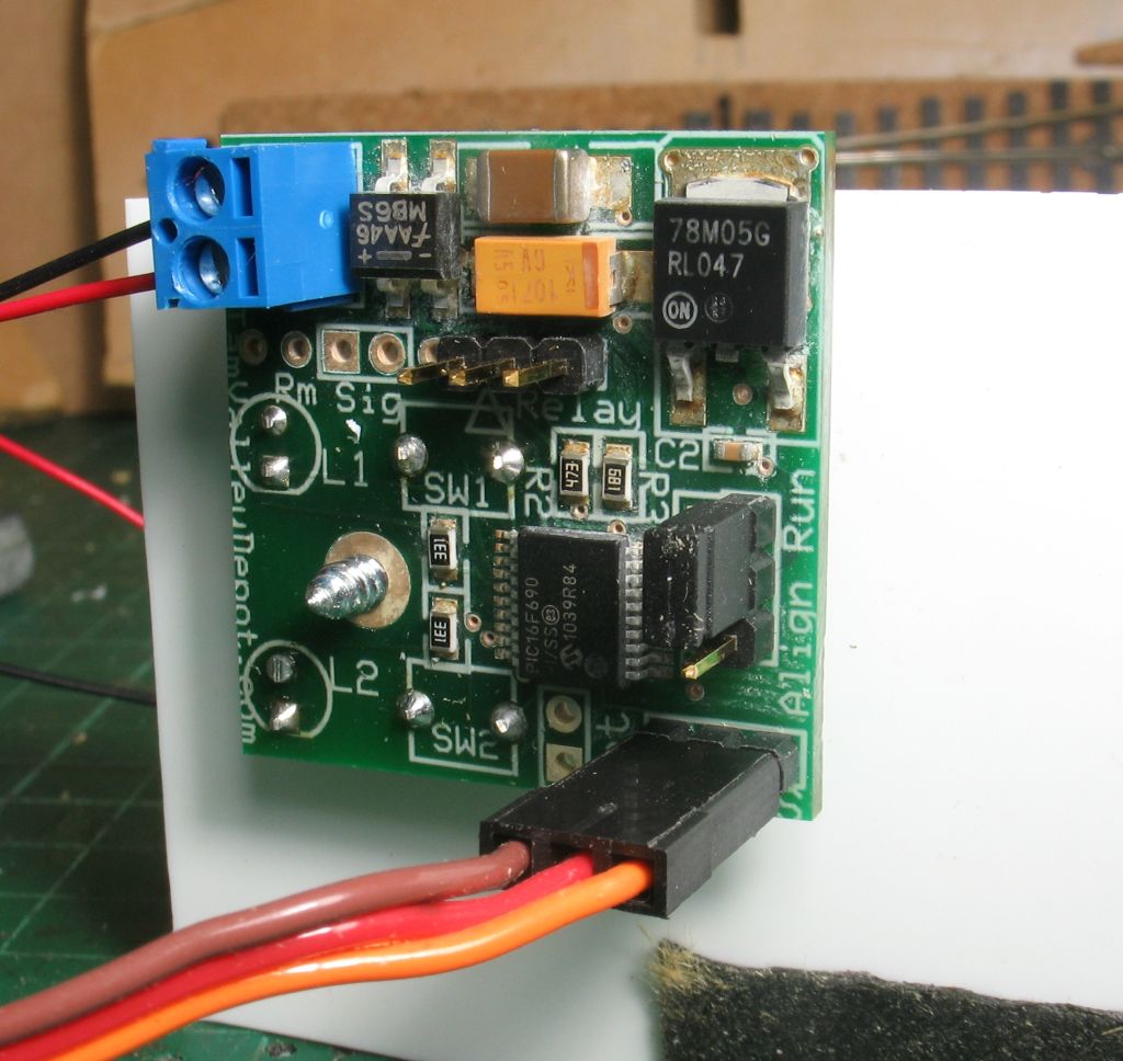
This board (Tam Valley Singlet II) has two screw terminals for the power input, this can be any AC/DC supply of 7-18 volts, OR, straight to the DCC bus under the layout. This driver board has two push buttons and two bi-colour LEDs for operation, a jumper plug for set up, and provision for a remote switch or push button. The bonus of using this board with DCC is that it has a built in accessory decoder so that you can operate the turnout (point) from your throttle. Once the servo is mounted and the power applied to the board the rest is easy.
Move the jumper plug to the “align” position and sit back. The LEDs on the board will flash and the servo will start to move one way. When the point rail gets to the stock rail and feels a mechanical resistance the LED will flash slowly and then stop. The point blades will repeat the process at the other rail. When the process has finished put the jump back to its “run” position and the servo is ready to use.
There is no soldering required and no technical knowledge – less knowledge required than wiring a Tortoise or similar. The board is supplied complete or as a “kit” the kit contains the ready made up and tested board, two LEDs and two push buttons for you to solder on either the front of the board or the back. Alternatively, the LEDs can be mounted on the facia panel of the layout.
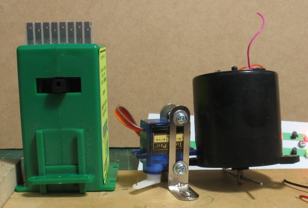
The above photo shows the servo vertically mounted alongside a Tortoise to show the relative size.
None of the above requires soldering just plug the bits together. If the cables are not long enough there are also 300mm, 600mm, and 1200mm extension cables that just plug in – no soldering.
The TAM Valley Singlet can also be adjusted using Decoder Pro.
ANE also make a driver board that can handle 4 Servos with an extra board as a decoder.