By Laurie McLean MMR
To answer some questions I have received regarding how I do my Classification Marker Lights on my Hon3 locos you will find below the hints & tips that I hope help you to give it a go on your little girls.
This is pretty tiny stuff we are dealing with and my Sony Cyber-shot camera doesn’t get in super close to see the details as good as I would like however I think the photos will provide you with what is being discussed to be useful.
Who makes the Surface Mount LEDs for trains? Richmond Controls in Texas. Jim Hinds is a very helpful fellow.
What colours are available? = Golden White, Sunny White & red, plus other colours – see the website
What sizes are these SMLs? = 0.8mm but you can get them with the tiny enamel wire already soldered to the pads that make it much easier to work with & recommended by me for first-timers attempting this.
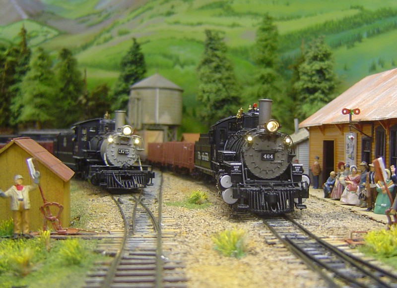
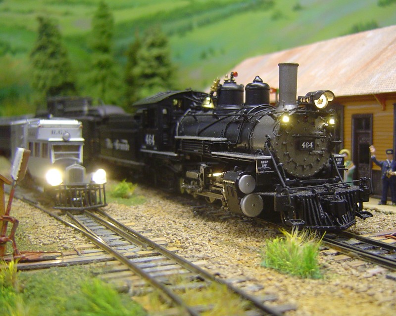
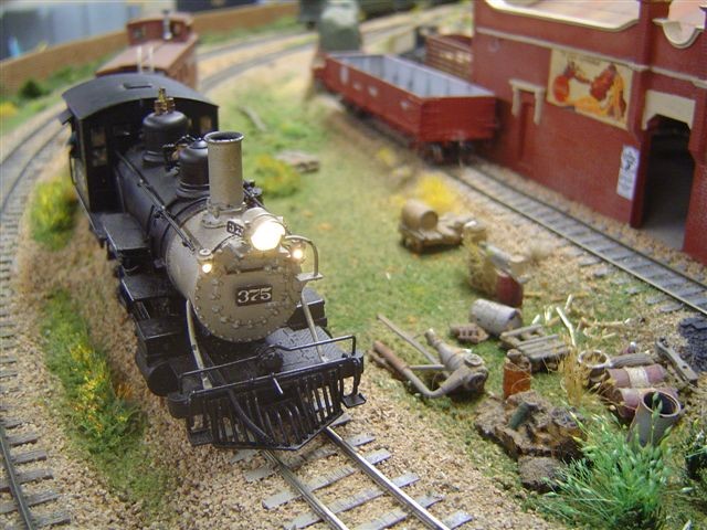
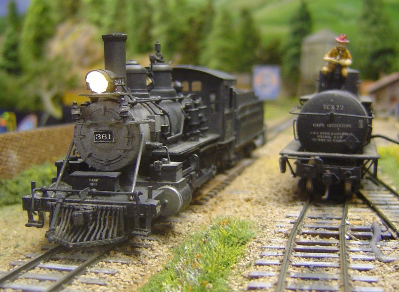
Both locomotives with the classification marker lights and headlights use SMLs.
Inside the cab of the K27 is another SML that shines down on the back-head gauges, this being 4 each SML’s fitted to this loco. A 5th could be fitted for a reversing light on the tender.
I think you would agree they look good and the picture doesn’t do them true justice but it’s the best I can provide to give you the idea of how these SML appear on the layout.
All the lights are “Golden White” SMLs on both locos.
There are a number of brass marker lamp detail castings available from various manufacturers but I like PSC’s as they have the hole cast into them. (Figure 2)
The PSC part number is 3124 and with a little cleaning up, the hole accepts the tiny SML beautifully.
The PSC catalogue shows them on page 107 and there are a lot more to choose from. For headlamps and tender reversing lamps see page 71 in the catalogue.
The headlamps are made in brass and plastic & the plastic may be an easier material to work with as drilling out existing headlamps on brass locos is a very delicate matter where a lot of care & time is required, plus the right tools.
I use a brand new 0.025” drill in a pin vice to make the pilot hole in a headlight on my locos & then use several more drills increasing in size a tiny bit at a time to open out the hole until it is a 1.0mm hole is what I end up with to accept the tiny SML in head or tender lamps & square the inside with a needle file to suit the square shape of the SML in the BACK of the lamp casting.
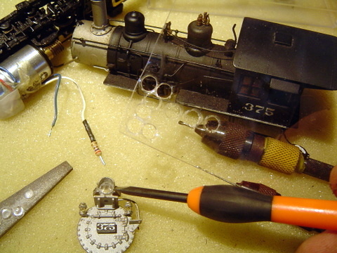
In this next photo, you can see the headlight glass lens I made for the C-25 loco from clear styrene using a wad punch.
The resistor can be seen soldered to the white decoder wire.
I punched out several round discs and chose the best from the bunch to use. It is held in place by white glue.
A number of manufacturers make headlight lenses but I like making things myself as it saves money and I learn new skills and can say “I made it” which gives modelling satisfaction.
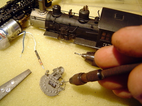
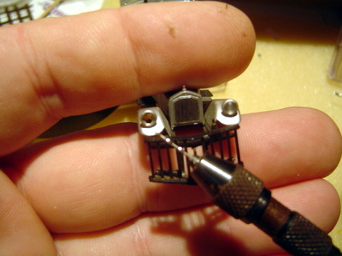
Figure 4 shows the original marker lamps fitted to the Westside model. In this case, they were solid brass so holes needed to be drilled straight through them facing forward. As can be seen, the smoke box cover was removed for safety and ease of handling. I use a soft sponge sheet to work on so the model is protected from scratching its paint but it also helps take the pressure when drilling the hole.
There is no hurry, for if it is rushed the tiny casting may be torn off so this is a “take your time” bit of modeling.
A brand new 0.020” drill was used to drill the first pilot hole then successive step-up drills to 1mm used until the SML was able to fit into the back of the lamp.
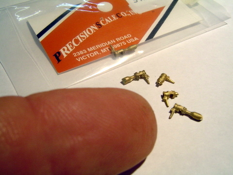
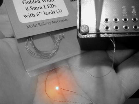
This photo shows the actual size of the SML – tiny heh?
The packet shows the information, in this case I purchased from Gwydir Valley Hobbies in Australia who sell the Richmond Controls items.
That’s the SML shining bright in the palm of my hand with the 6 inch enamel wire leads connected to my LED tester.
Notice how the wire is coiled in the packet. It is very easy to snap this tiny wire so it is recommended to keep the excess wires coiled inside the body of the model and don’t cut the wires.
Each SML with the 2 x leads has one lead longer than the other and both lead ends are “tinned” ready to solder to.
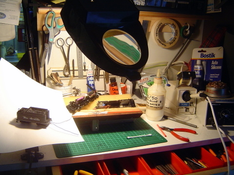
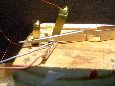
Here’s my little work bench and there is an overhead light plus a magnifying glass lamp.
Notice the soldering iron – it’s a variable temperature unit & the tip used to do all the soldering work on sound decoders and these SML’s is a 2.5mm diameter tip with a fine point. It is very important to use just a low temperature so the insulation is not burnt on the tiny wires & by keeping the wires with just a very small “tinned” end showing from the insulated wire there is less risk of an electrical short.
I always tin the wire end then trim it to a short length before soldering it in place.
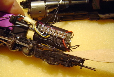
The use of Printed Circuit Board (PCB) is a good way to make your own terminals. The PCB terminal can be glued inside the loco and because the fibre with the copper shim pads insulates the terminal it suits the purpose for joining parts at one point.
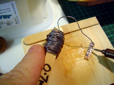
With sound decoders and the wires for the lights, it makes things easy to use this type of terminal. The decoder wires are soldered to one end of the “tinned” copper pads and the SML wires can also be soldered to the other.
Once installed in the loco, I usually glue the terminal onto the motor, the whole terminal can be covered with a thin insulation tape to prevent it from touching the metal body of the loco, usually the boiler. Here too you make it yourself & it works very well.
Figure 8 shows a SML on my MMI K27 installed in the cab and the other 3 sets of SML wires from the headlight and front marker lights. The 4 x SML leads have been run inside the boiler roof to clear the motor and gears. The thin tape holding the wires in place.
Notice that the space in the very front at the smoke box is where the wires are. The excess enamel insulated fine SML leads will be coiled together and gently fitted inside the front area.
This keeps them protected and for maintenance, there is a need to move them as they are so fine they can easily be damaged. I used standard #30 decoder wires to run to the SML lead ends & used heat shrink over the joins. The larger #30 wires have just enough length so as the boiler can be safely removed.
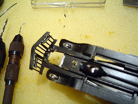
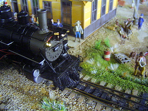
The next photo shows a Lambert Pierce Arrow Goose #4 with the headlight lens removed & a hole drilled on the left side for a SML. In this case the angle to work required the hole to be downwards and the SML fitted inside the lamp body. White glue was used to hold it in place.
The standard 3mm LED’s were too big for this application.
On the right in figure 10 the underside of the goose can be seen where the SML wires need to come out from the back of the headlamps and the wires were made to run following the underbody and into the freight car body where the decoder is installed.
Figuring out the best way to drill the holes for each installation is the trick and to make it so it is least noticeable and so the model remains looking correct. Its time consuming doing this tiny stuff but the rewards of a fine working model is worth the efforts.
Here’s the finished goose with the bright lights – the camera over emphasising their glow in this shot.
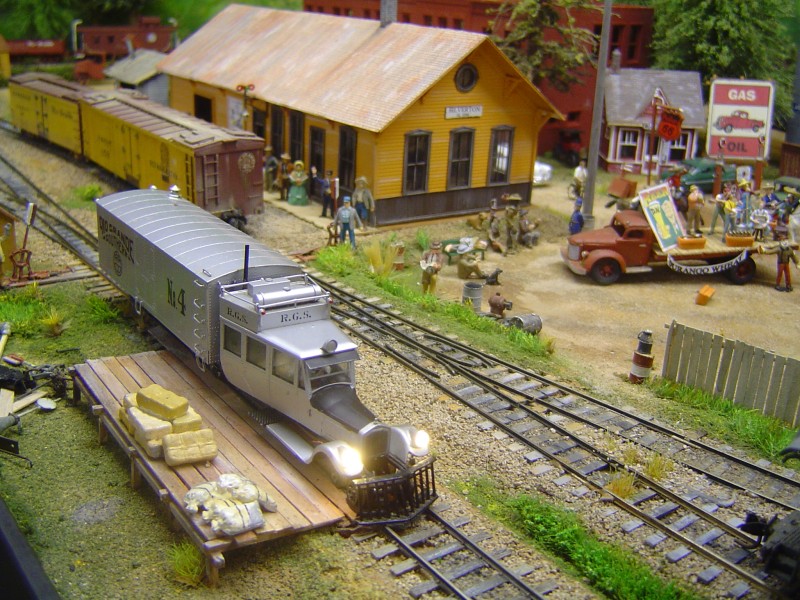
But what a difference adding the lights makes to the model.
Adding sound has made our Hon3 hobby even better and with the decoders, the functions to turn the lights on or off and horns beeping takes the enjoyment another step further.
It’s such good fun.
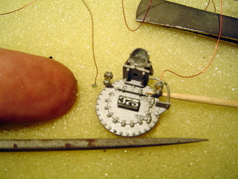
The photo on the right (fig 12) shows the C-21 with the 3mm hole in the headlight. I chose to replace the 3mm LED with a SML, the same as the 2 x classification markers so I could use the one (1) resistor for all 3 SML’s.
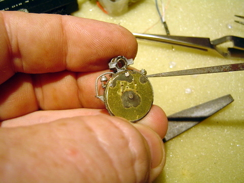
I am using a tapered square shaped needle file to make the tiny square in the BACK of the marker lamps in this photo. By working from the back to accommodate the body of the SML the front hole remains small.
Gentle pressure being just enough to remove material is required so as not to cause damage. It make you appreciate what a watchmaker or jeweler has to do in their jobs every day!
Now we can start to fit them into the holes we drilled and filed out.
The SML has been installed in the right hand side marker and the headlight has been glued onto a piece of black styrene and is being held in the tweezers ready to install in the back of the headlight.
The wooden toothpick is wedged against the SML while the white glue sets. It is necessary to work out a way of holding these small lights in the brass markers bodies to allow the glue to work and set. Leaving them overnight for the glue to dry and keep them in place makes them secure enough to continue working without them coming adrift.
The headlight glass lens has been made and glued in place already.
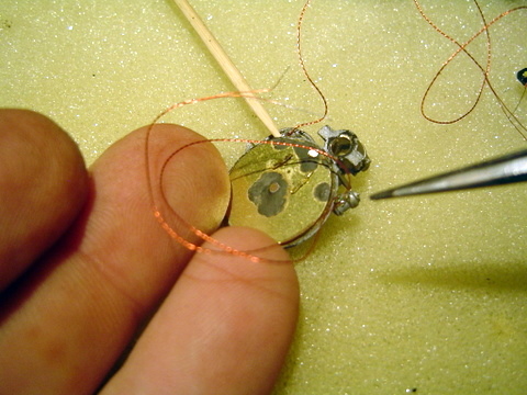
The left hand side SML has been fitted in this next photo and notice the wire leads are everywhere.
Working with these tiny wires hanging about is no real problem, just let them be as you work and trying to keep them coiled like they are in the packets helps.
The toothpick is still holding the other in place and another toothpick will be fitted to this one and left overnight.
Working on the sponge, the enamel wires don’t get scratched so the insulation remains in place.
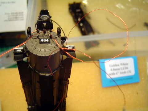
The front end of the K-27 shows the 3 x front end SML’s installed.
The original headlight grain of wheat globe hole underneath can be seen and this hole was used to run the SML leads through and to be gathered up with the 2 x marker light leads so they all go through the same single hole in the front.
Wrapping these wires all together does not hurt as the enamel insulation, although very thin, is sufficient to work in this situation.
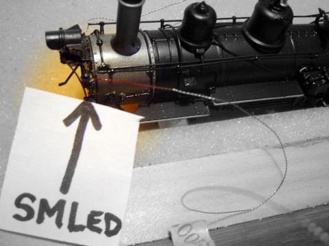
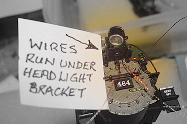
Figure 17 shows the side view with the SML lead coming out the back and the white glue of course has dried and is holding SML secure in the back of the marker lamp. Working with the leads is best accomplished using tweezers to maneuver them into the desired “run” required. They are not brittle and can bend very easily and care is needed so they don’t “knot” which makes it impossible to feed through the hole into the body.
The ends of the leads come already “tinned”, and as mentioned earlier; one wire is slightly longer than the other. It is the short wire where the resistor needs to be soldered onto. If you look back to Fig.3 you can see the resistor soldered to the WHITE decoder wire. All the decoders I use for my narrow gauge steam locomotives are Soundtraxx Tsunamis, either the DSD 1000 or the DSD 750.
Always place heat shrink tubing over solder joins or wire joins to prevent shorts. It’s a good idea to have a range of resistors to choose from so the light intensity can be perfected to suit the loco to get some variety so each loco is slightly different to others. You can see the Goose has bright lights, well the workshops just did an overhaul on her and her paintwork is new too. So in this instance, the Goose is in “tip top” condition. On the steam locomotives, it’s the opposite, their lights are somewhat dimmer looking and the yellowish tinge is apparent. The value of the resistor makes these changes and it can all be done on the workbench before final reassembly. What resistor values? Well, I start with a 1/4 watt 1k value and then try a lesser or greater value. My box of resistors has 270 to 3k values and I have found I can get the exact light effect desired from these. It does not matter which way the resistor is soldered as they are not directional.
I’m certainly not an electronics guru, I just use the items and ask questions to further my knowledge, but by attempting to do this electronic/electrical work I am always learning & becoming confident.
The only mistake I have made in doing this work was to solder a wire on SML while the DCC power was on to the loco & I got a surprise when a pair of them went “pop” and let out a puff f smoke. They were replaced and I learnt a valuable lesson.
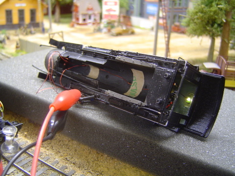
Fig.18 shows the terminal I made and glued to the motor and the 2 x with SMLs can be seen having just enough length so as they can be tucked away in the boiler – a tight fit but it works fine.
The photo here shows the loco on the track for the first time and the lights turned on.
As you can see there is light coming out from the back of the marker so some black paint will be applied using a “00” artist brush to cover the leaking light.
To make the glass lens for the markers matt medium can be used by placing a tiny “dob” in the front hole and if it touches the SML it doesn’t matter as it dries clear. This can also reduce the light intensity too & several layers can be built up. I use a toothpick to place the medium.
I have not tried gloss medium however this would work also just as well.
Here is the end result of the work and even though the camera is making the goose lights appear brighter because of the conical headlight lenses that were factory original, the differences can be seen.
The headlight on the locomotive is just right to me and you can see inside the lamp and it actually looks as if the filament of the electric globe can be seen – you can’t get this in Hon3 with a 3mm LED.
All of these have the 0.8mm SMLs fitted.
Figure 23 shows a “Sunny White” on the left & a “Golden White” SML on the right. You can see the size difference of the wires on the PCB. The sunny white is white with no blue tinge and the golden white has a slight yellow tinge. There is a difference but it doesn’t show well in the photo.
I hope this has been of assistance to you. It’s a lot of fun!
Regards,
Laurie